
 The Watt’s Electricity project has unexpectedly emerged from a random convergence of unplanned life experiences and unrelated interests. I wanted to keep the story succinct, but the numerous component parts means that has been difficult!
I have always had an interest in electrical gadgets, my mother has quoted too many times, the need to remove me from Woolworths aged 3 because of my embarrassing “I want a battery” screams! I blame the purchase of the Ladybird book Magnets Bulbs & Batteries which lead to studying electronics at college where I was sucked into the amazing world of Amateur Radio.
My career as a main frame computer operations analyst accidently pushed me into an educational environment that took no prisons. When explanations were not clear, straight forward and lively, the computer operators that had been dragged off night shifts for the course, would let me simply by falling asleep!
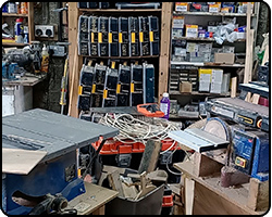
 In parallel, down time was spent pottering in my father’s workshop which had its own magnetic attraction to salvage, over stuffed from a mind-set that nothing should ever be thrown away. Started by his father in 1936, it haven’t moved location or been spring cleaned for over 80 years. The result was paradise - every conceivable tool or material that came into thought could be accessed by just raising a hand.
Here is a poem about the workshop.
In parallel, down time was spent pottering in my father’s workshop which had its own magnetic attraction to salvage, over stuffed from a mind-set that nothing should ever be thrown away. Started by his father in 1936, it haven’t moved location or been spring cleaned for over 80 years. The result was paradise - every conceivable tool or material that came into thought could be accessed by just raising a hand.
Here is a poem about the workshop.
The next relevant part of the story was an interest in photography turning into a second career which resulted in running adult education classes for the local council. The role came with compulsory formal educational training on the anatomy of learning.
Unrelated at the time, I had a part-time job at the local B&Q where I was heartbroken to discover the off-cuts from the timber saw cutting service were thrown away - unforgivable! Soon I left every shift with a trolley of what they called scrap, often accompanied by heavily discounted end-of-line hardware. Stock I knew would come in handy one day.
I fast forward to our arrival in Orkney complete with all the screw boxes, timber and the contents of my departed father’s workshop to final part of this meandering story. The eureka moment was while surfing (as we used to call it) online and unexpected discovering the jaw dropping low prices of electronic components available direct from China. In my college days, the only meter available to the whole class was a single AVO weighting in at 3 kgs and costing £70 second-hand! Now an unmounted panel meter was an affordable £2 and a whole multi-meter for just a mind-blowing extra £1!
At last, I could solve the problem we had at college that was left completely untethered, electronic students burnt through components at a ridiculous and unsustainable rate with the addition hazard of some of them exploding right in front of our eyes! But these problems could be solved by hard wiring circuit examples on the B&Q plywood and surrounding key components with the cheap panel meters giving a visual aid as to what was going on in the circuit. Switchable options would create the ability to change the circuit and allow experimental play but without the risk of components turning into fireworks. It could all make this incredible world far more accessible in a simple and safe way and enable experience to be gained before going free-style.
After the construction of the first board, the next 46+ were just an obvious extension of the same logic.
James Barry
The image here shows the last board in the electronic components section before it moves into integrated circuits. It features an astable transistor multivibrator circuit. Previous boards have explained how resistors, capacitors and transistors work and that is all pulled together here. To make the circuit easier to understand, 9 meters have been added. 1 showing the supply voltage, 4 giving the current flowing through the each of the resistors and the other 4 giving the voltage of each side of both capacitors.
The inclusion of the switches mean that we can start without the capacitors and one transistor switched off. Only when the circuit in this state is explained do we switch in the 2nd transistor and then each capacitor in turn. This approach makes it much easier to understand the circuit as we can build it up step by step. Making the 2 key resistors variable introduces another way the circuit could be changed altered. Op-amp voltage followers on the voltmeters mean they could be added without affecting the circuit. Note that I have blacked out the last two digits on the digital meter, I have does this with them all because it makes them easier and simpler to read. The extra digits are not required and as they have a habit of changing, it is a destraction.
Safety has always been a key factor in the design of the boards. An example on this board is the use of bi-polarised capacitors. This is because if C1 is switched on and the Q2 switch is off, the capacitor is being reverse charged by a few volts and a conventional electrolytic capacitor could pop.
Boards | 48 |
AA Batteries | 132 |
Switches | 156 |
Panel/Digital Meters | 98 |
Oscilloscopes | 2 |
Electronic Components | 341 |
Tutorial Word Count | 16159 |
Tutorial Videos | 39 |